
Pixel Ortho
Pixel or Vector Projections generate 3D object

I saw a project from Pixel_Salvaje called pixzels. And was intrigued. Looks like magic, so I dove in, trying to understand how that’s possible.

Pixel Ortho is my take on that idea. The idea is that you already have clean orthographic drawings of an object; the app can use them as constraints to produce a simple 3D result. It lacks the polish and options of the original, but it’s a good starting point for them to be added in the future if needed. Pixzels is a paid version after all.
The pixel workflow starts with bitmap projections. These are flat images of the same object from orthographic directions: front, left, back, right, top, and bottom.
The minimum useful setup is usually front, left, and top. Front gives width and height. Left gives depth and height. Top gives width and depth. Once those three planes are aligned, every possible x, y, z position inside the grid can be tested.
I took ambulance projections to test out the app without asking; hope no one will get mad about that.
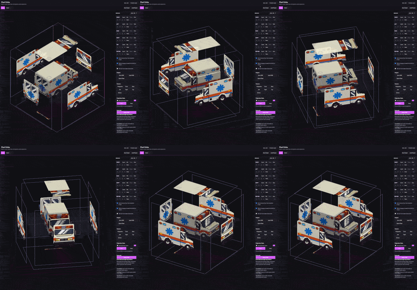
The test is simple. Front says this x/y position is occupied, left says this z/y position is occupied, top says this x/z position is occupied; if all active shape views agree, keep the voxel. That creates a voxel volume from the intersection of projections. The output is intentionally mechanical. If the input views line up well, the model reads well. If one view is shifted, scaled differently, or drawn from a slightly different angle, the intersection shows that immediately.
The voxel mode uses a shared square grid. 128 x 128 is usually the practical upper end for detailed sprites. Smaller grids are faster and cleaner for rough forms, icons, and early tests.
There is also an auto-size option. When “Auto-size grid from first imported image” is enabled, the first imported bitmap sets the grid size from its largest dimension, capped at 128. Later imports use that same grid. That matters because all views must share one coordinate system. If the front image fills the grid and the side image is tiny within it, the generated result is not wrong from the app’s perspective. It is doing exactly what the projections asked it to do.
Bitmap imports use transparency as the main signal. Transparent pixels do not create voxels. Opaque pixels do.
The preview and export do not create one separate cube mesh per voxel. The app builds one surface mesh by checking neighboring voxels and emitting only exposed quads. Internal faces are skipped, which keeps the result smaller than a naive cube-per-voxel model.
The exported GLB contains the generated geometry, vertex colors, and one material using those colors. It does not include the reference planes, source files, UI state, or project JSON.
Voxel mode also includes projection painting. Choose `Edit` on a source projection, then paint or erase pixels directly on that projection.
This is not a separate texture paint system. Editing the projection changes the source pixels, so the voxel shape and the sampled surface colors rebuild from that edited projection.
That is useful for quick fixes: closing a gap, erasing a stray background pixel, moving a silhouette toward the result you actually intended, or checking how a small projection change affects the 3D volume.
Currently, those edits are not saved to disk or edited on the original input, but that’s an option that will be added in the future.
I wanted to see if similar thinking can be made using vectors. Something like AmbigramGenerator.

The vector workflow is separate from the voxel workflow. It starts with filled SVG projections and builds a vector visual hull.
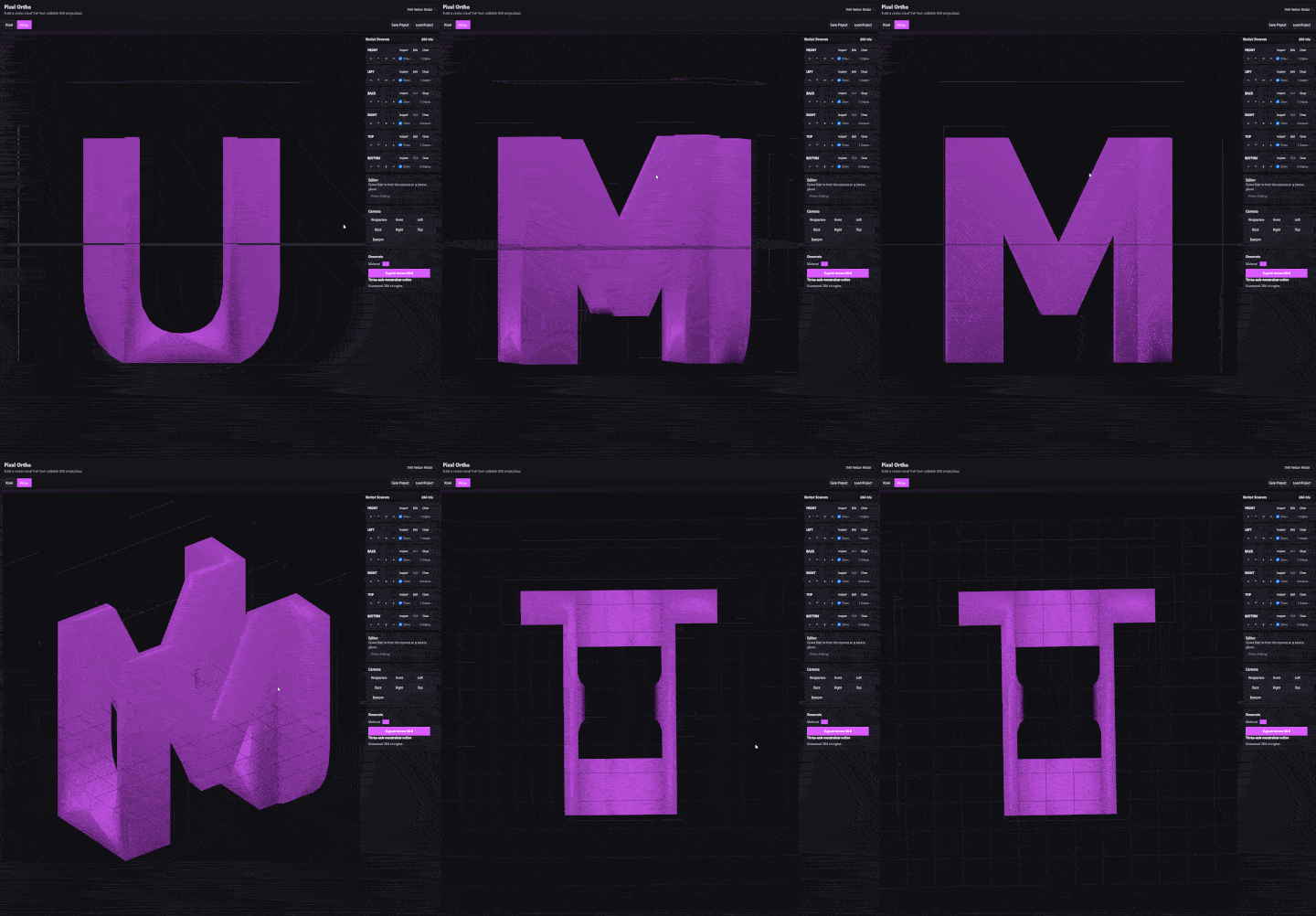
Instead of turning pixels into occupied grid cells, the app parses closed filled SVG shapes, flattens curves into polygon contours, extrudes each projection through 3D space, and intersects those extrusions.
Vector mode supports filled closed geometry. Unsupported content is ignored with a warning. That includes strokes, open paths, clipping, masks, filters, and text.
The important detail is that strokes do not constrain the model. If a line needs to affect the result, it has to be represented as filled geometry.
When you select “Edit” on a vector source, the camera locks to that source plane. The white points are anchors. The purple points are Bezier handles. Dragging an anchor also moves its attached handles. Dragging a handle changes the curve. The source path updates during the drag, and the final Boolean mesh rebuilds when the edit is committed. Vector sources also have offsets and visibility toggles. Visibility matters because only visible vector projections participate in the generated mesh.
It could be interesting to add more features to it, but for now I’m satisfied; my itch was satisfied. A working base is here.