


Art-net, WS2812 and ESP-01
Clearing out stock of old microcontrollers by using them

Ever since it first came to the market in 2014 the Espressif Systems chip ESP8266 has become the favorite WiFi enabled microcontroller. When it came out there were no mentions of it online except in the HackaDay article but today, there are millions of articles and projects that are based on this chip or its successors like ESP32.
There are many variants of ESP8266 but the basic one is called ESP-01 and can be found for less than $1. As years passed and the ESP platform became more capable the basic, old, ESP-01 was left by the side. It is still capable and the major difference between it and its younger brethren is that it offers only 2 control pins or 4 if you will not use TX and RX pins. As they are all over the lab, uselessly sitting on shelves it was time to use some of them.
Update:

The decision came to make a backlight for my work table.
Code used was from user Bob “mcnobby” Lynas from Arduino forum and his post about ArtNet to WS2812 Pixel LED driver : Using Wemos D1 (arduino-esp8266), with some small modifications.
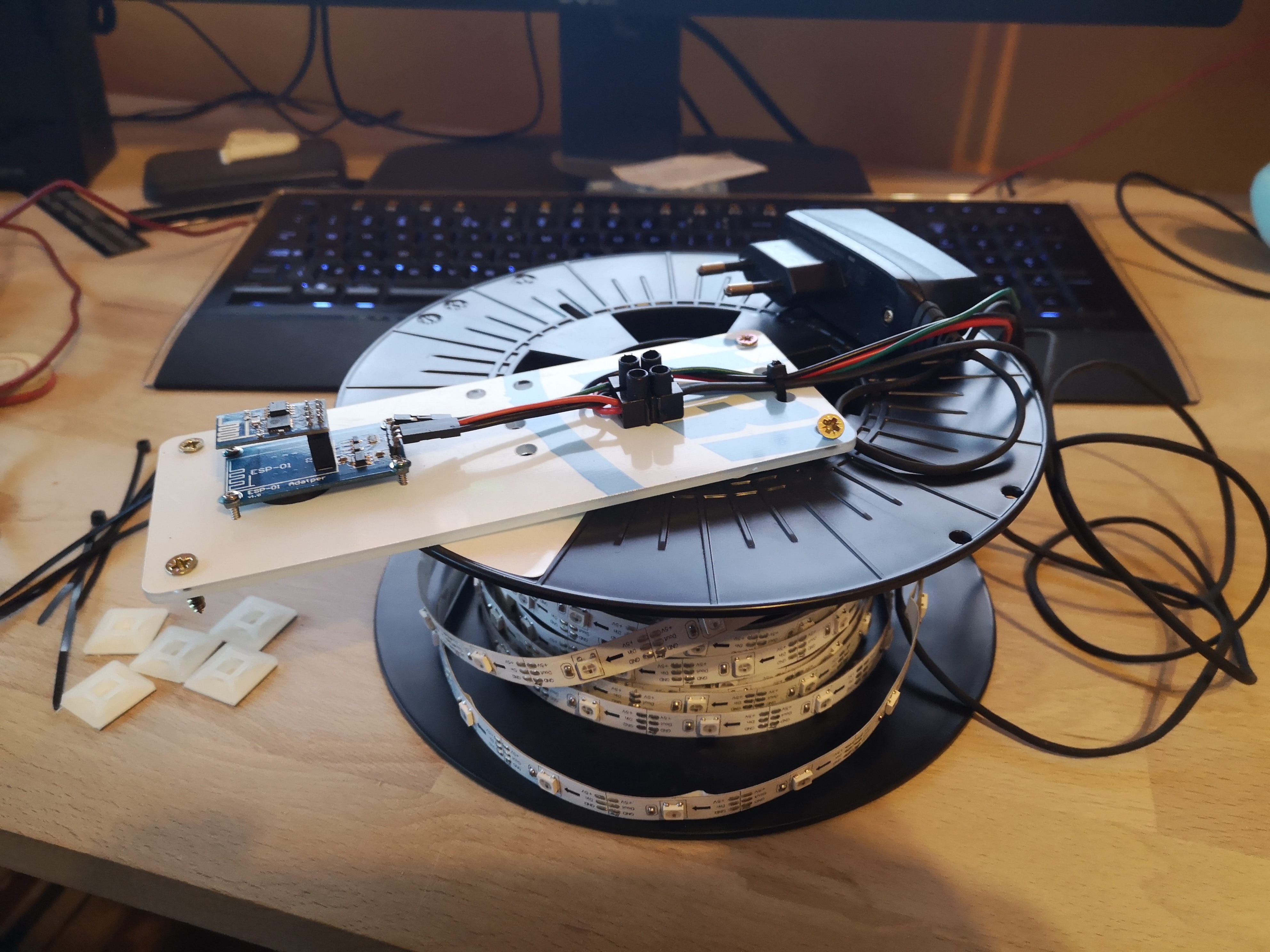
As ESP01 has no current or voltage regulator onboard and ESP-01 adapter board was used but it has only RX and TX pinouts alongside Power and Ground pins. GPIO1 and GPIO2 can be used by soldering to the board but why destroy the esthetics of a perfectly good adaptor board with even more wires when we can remap RX pin which is not used anyway to do the function of GPIO.
//********** CHANGE PIN FUNCTION  TO GPIO **********
//GPIO 1 (TX) swap the pin to a GPIO.
pinMode(1, FUNCTION_3);
//GPIO 3 (RX) swap the pin to a GPIO.
pinMode(3, FUNCTION_3);  //**************************************************
By doing this only for RX pin we can still use TX pin for debugging. In the code, we change the WSout constant from 5 to 3 which represents RX pin on ESP8266. Additional changes need to be made to the code like the Router SSID, password, and other WiFi network related stuff but nothing more. It is a refreshingly straightforward process.
There are many Art-net/DMX/E1.31 control programs out there but the ones we used in the lab the most are Glediator and Jinx. Sadly, Glediator disappeared along with its site solderlab.de. It’s a shame as it was a good program. So, we are left with Jinx!, another German software.
Once installed go to the Setup menu and Output Devices. There select Art-net, deselect the broadcast checkbox and enter the IP address of your ESP.

Next, we need to create a patch, for now, any patch will do and you can play around with different configurations later. Go to the Settings menu and select Output Patch. If any existing patches exist click Clear Patch and then Fast Patch. In the dialog enter desired dimensions, any dimension will do just have in mind that the total from dimension should be equal to the total number of LEDs you have. Make sure that the First Channel is set to 0 and then select the Patch Device that we have created earlier.

That’s it! Select your effect from Channel 1 Effects panel, go to Setup and click Start Output.

If colors look wrong change Pixel Order in FastPatch dialog until they light up correctly. You will need to start from scratch, Clear Patch, and apply Fast Patch again with different Pixel Order. Once everything is working correctly you can play with different matrix sizes, patches, and patch modes.
A more advanced version of this is making the entire table out of addressable LEDs.